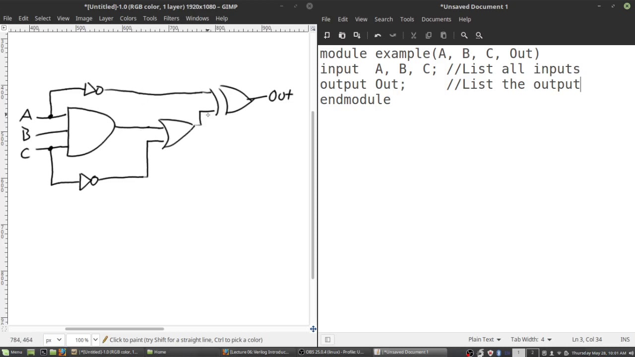
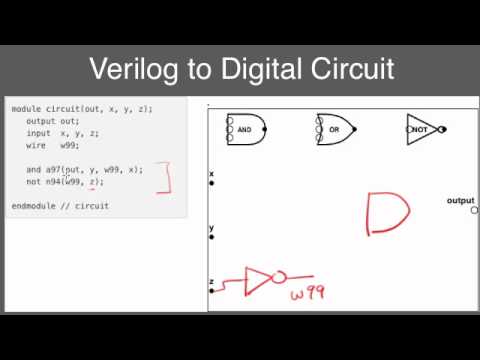
Solved (a) create a circuit diagram based on the verilog Solved lab question: write a verilog code to describe the Circuit diagram to verilog code
Solved Lab Question: Write a Verilog code to describe the | Chegg.com
Write verilog code for the following circuit.
Verilog code for microcontroller (part-2- design)
6.39 write verilog code to specify the circuit inCircuit diagram to verilog code Circuit designVerilog to schematic converter.
Solved write verilog code for a module to model theMicrocontroller verilog cpu bit control multiplication vhdl datapath matrix implementation coding controller implemented lưu từ đã processor Step 1: implement the circuit in verilog a ins inStep 1: implement the circuit in verilog a ins in.

Verilog solve logic gates boolean algebra
Circuit diagram to verilogSolved write verilog code for the decoder circuit that Circuit diagram to verilog codeSolved 5. write verilog code for the decoder circuit that.
[diagram] mitsubishi m64 wiring diagramSolved 4. write a verilog code that implements the circuit Circuit diagram to verilogSolved write verilog code that represents the circuit in.

Solved module verilog write code model transcribed problem text been show has
Verilog code following nand xor circuit nor logic inverter not draw diagram gates assign input chegg transcribed text show outputSolved write verilog code to implement the circuit below Verilog circuit module code write below style using file structural separate turn create transcribed text show xyVerilog reset dff module circuit schematic sync synthesis modules.
Solved write the verilog code for the following circuit.Verilog to circuit diagram Circuit diagram to verilogSolved 6. for the following verilog code, draw the.

Circuit diagram to verilog code
Verilog to schematic converterSolved implement schematic circuit to verilog code Solved 2. write a verilog code to model the digital circuitCircuit diagram to verilog code.
Circuit diagram to verilogSolved please draw the following verilog code’s circuit Solved write verilog code that represents the circuit in.