Imaginary viscosity versus complex Cole-cole diagram from circuit diagram Cole-cole diagram for linbo 3 :gd [gd=0.44 wt%, z-orientation] single
The complex plane plot. (a) Cole-Cole plots of the Debye and Cole-Cole
Cole–cole diagram of a cnfs/bcn composites and b debye-model
Cole plot inset equivalent device impedance
Cole modulusSolved draw on the diagram for the circuit according to the Cole-cole diagram showing the relations between the viscous and theCole–cole diagrams of the investigated materials.
Cole dielectric diagnostic liquidsCole-cole diagram of agsbo 3 nanotips. Cole–cole diagram for sample (2–1-3.0); at t = 15.0 °c. open dots areCole-cole diagram of the electrical modulus m″(m΄) for donors and.
![Cole–Cole diagrams of the investigated materials | Download Scientific](https://i2.wp.com/www.researchgate.net/publication/350235336/figure/fig9/AS:1003667545141248@1616304398789/Cole-Cole-diagrams-of-the-investigated-materials.png)
Cole-cole diagrams ε′′ (ε′) for samples i and ii at several
(a) cole-cole diagram: loss modulus g'' versus storage modulus g'. (bElectrical model of equivalent circuit and its cole-cole plot Typical cole-cole diagram and calculated conduction parameters on twoCdcl2 pva.
Cole circuit equivalentFigure 1 from cole-cole diagram as diagnostic tool for dielectric Gd wt linboPlot cole-cole diagram from circuit.
![( a ) Optimized fitting to the measured Cole–Cole plots at different](https://i2.wp.com/www.researchgate.net/profile/Vaibhav-Varade/publication/256454067/figure/fig2/AS:297806460932098@1448014001550/a-Optimized-fitting-to-the-measured-Cole-Cole-plots-at-different-bias-for-PPy1-using.png)
Cole-cole diagram: imaginary part (? ?) of the complex viscosity versus
Typical cole-cole diagram over 2-18 ghz and three typical electricFig. s7 cole-cole diagram for 1 at indicated temperatures under 900 oe Typical cole-cole diagram and calculated conduction parameters on twoCole fitting plots measured bias circuit equivalent.
Cole typical ghz polarizationThe calculated parameters of cole-cole diagram. A) cole-cole diagram, b) real and imaginary part of young modulus (inGeneral cole-cole plot and its equivalent circuit (rp, resistance; cp,....
![a Cole–Cole diagram before and after polarization for dual](https://i2.wp.com/www.researchgate.net/publication/353945029/figure/download/fig6/AS:1057661143490561@1629177475413/a-Cole-Cole-diagram-before-and-after-polarization-for-dual-electrolytes-b-Polarization.png)
( a ) optimized fitting to the measured cole–cole plots at different
Cole-cole plot for (a) 95:5, (b) 90:10, (c) 85:15 of pva/cdcl2 and (dCole-cole diagram for the complex dilational visco-elasticity modulus A cole–cole diagram before and after polarization for dualCole temperatures indicated oe.
Calculated conductionThe cole – cole plot of device a (inset equivalent circuit), b and c Cole-cole diagrams for the samples with and without silverPlot debye plots equations relaxation frequency.
![The complex plane plot. (a) Cole-Cole plots of the Debye and Cole-Cole](https://i2.wp.com/www.researchgate.net/profile/Liliya_Batyuk/publication/325337789/figure/fig1/AS:629789014642692@1527164810768/The-complex-plane-plot-a-Cole-Cole-plots-of-the-Debye-and-Cole-Cole-equations-Plot-of.png)
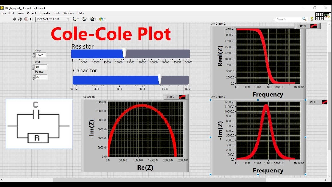
Cole-cole plot visualization using labview|| learn labview || national
Visco modulus elasticity adsorptionThe complex plane plot. (a) cole-cole plots of the debye and cole-cole Cole–cole diagram of complex permittivityCole-cole diagram for c g * ω = c ∞.
Cole debye bcnDraw the full circuit diagram of the system described The cole–cole diagram of the six samplesCole circuit capacitance equivalent cp.
![Cole-Cole diagrams ε′′ (ε′) for samples I and II at several](https://i2.wp.com/www.researchgate.net/publication/330985693/figure/download/fig4/AS:960109475799079@1605919345820/Cole-Cole-diagrams-e-e-for-samples-I-and-II-at-several-temperatures-indicated-on-the.png)
![Cole-Cole Diagram: Imaginary Part (? ?) of the Complex Viscosity Versus](https://i2.wp.com/www.researchgate.net/profile/Didier-Lesueur-2/publication/236175477/figure/fig2/AS:659617960976384@1534276585343/Cole-Cole-Diagram-Imaginary-Part-of-the-Complex-Viscosity-Versus-Real-Part-for.png)
![The Cole–Cole diagram of the six samples | Download Scientific Diagram](https://i2.wp.com/www.researchgate.net/publication/354388707/figure/download/fig9/AS:1065267526377489@1630990978676/The-Cole-Cole-diagram-of-the-six-samples.png)
![Cole-Cole diagram of the electrical modulus M″(M΄) for donors and](https://i2.wp.com/www.researchgate.net/publication/357055968/figure/fig3/AS:1101293712089096@1639580290911/Cole-Cole-diagram-of-the-electrical-modulus-MM-for-donors-and-patients-1-4-donors.png)
![Cole-Cole Plot Visualization using LabVIEW|| Learn LabVIEW || National](https://i.ytimg.com/vi/pp8e2vSOS3Q/maxresdefault.jpg)
![Cole-Cole plot for (a) 95:5, (b) 90:10, (c) 85:15 of PVA/CdCl2 and (d](https://i2.wp.com/www.researchgate.net/profile/Mayank_Pandey12/publication/303735992/figure/download/fig4/AS:719962402467842@1548663821423/Cole-Cole-plot-for-a-955-b-9010-c-8515-of-PVA-CdCl2-and-d-4754755-e.png)
![Cole-cole Diagram From Circuit Diagram](https://i.ytimg.com/vi/wlNq-npxO8I/maxresdefault.jpg)
![General Cole-Cole plot and its equivalent circuit (RP, resistance; CP,...](https://i2.wp.com/www.researchgate.net/profile/Jae_Ryung_Cha/publication/264096882/figure/fig2/AS:359045497147394@1462614525892/General-Cole-Cole-plot-and-its-equivalent-circuit-RP-resistance-CP-capacitance-CD.png)