Circuit topology of a three-phase voltage source inverter with an lc Choke input lc filter Lc inductor voltage
What is the π-type RC and LC filter circuit identification method?
Filter basics part 2: designing basic filter circuits
Lc filter perform function does why where circuit electronics
What is filter circuit and its typesInductance to capacitance ratio in lc filter for pwm Capacitor inductor equivalent circuits panasonicLow pass filter diagram.
Lc resonant bandpass rlcCircuit lc filter diagram seekic basic Lc circuit parallel simpleImpedance matching filter circuit design – lc, l and pi filters.

Filter rc low components location matters totally yes capacitor
Lc circuit parallel circuits ac equations gif electricalacademia figure academiaBasic knowledge of lc filters Capacitor, inductor, lc, pi filter circuits for dc power supplyIntroduction to basic electronic circuits.
Lc band pass filter circuit diagramFilter circuits-working-series inductor,shunt capacitor,rc filter,lc,pi What is the π-type rc and lc filter circuit identification method?Lc filter.

Electric circuits
Band pass and band stop (notch) filterAnalysis of filter using lc circuit. Transfer functionFilter: calculating the transfer function of an lc filter made easy.
Lc pass high filter electronic circuits circuit basic introduction figureFilter pass low calculator lc rc voltage frequency passive high cutoff drop circuit order function capacitor reverse 2nd two measure Inverter lc topologyInductor rectifier capacitor lc circuits shunt.

Lc filter circuit diagram
Lc filter response circuit ltspice using schematic step circuitlab created stackLc low pass filter circuit Getting an rf low-pass filter rightLc circuit.
Need to understand how lc-filter works, help pleaseKapitulation fördern manöver pwm lc filter zeitgenössisch erweitert arm 6100lm filtering and chokeFilter circuit band lc bandpass pass notch stop series theory equivalent figure.

Circuit transfer function draw rc its lpf filter pass capacitor low
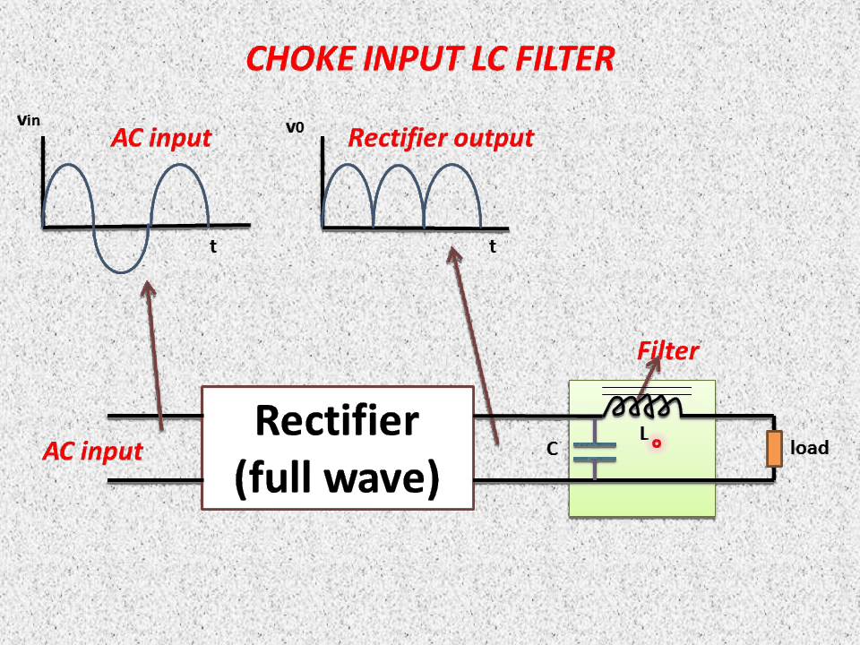
Capacitor circuit chokeChoke filter input lc Lc analogWhat types of emi filters are best for passing emc testing?.
Dictionary of electronic and engineering terms, half-wave rectifier circuitHow can i draw a circuit from its transfer function? Rc filter location of the componentsLc schematic circuit filter transfer function teaching filters circuitlab created using.

Lc filter circuit diagram
Filter lc schematic pwm capacitance ratio circuit using inductance circuitlab createdPassive components in ac circuits with equations Rectifier wave half circuit filter choke diode lc full circuits diagram dictionary electronic engineering gr nextWhat is series inductor filter? working, diagram, waveforms & formula.
.