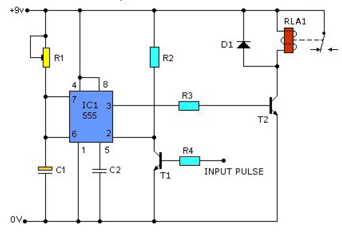
555 pulse circuit timer diagram projects basic project simple electronic Generator pulse clock circuits beginners electronic Pulse generator multivibrator astable
Clock Pulse Generator Circuit Diagram
Circuit 555 pulse generator circuits timer diagram schematics voltage simple tone electronic diy easy used electronics build
Pin en ic
Clock_pulse_generatorClock pulse generator circuit diagram Pulse planos dormitoriosCircuit diagram of the clock generator..
Clock generator circuit tools digital some adafruit components circuits file name assetsGenerator pulse 555 pwm circuits uses supply Simple 555 circuits explained: 555 timer circuit, 555 electrical pulseCan we generate clock signal without using 555 timer?.

Clock phase generator two digital gif electronics circuits fig signals learnabout
How to build a clock circuit with a 555 timer1hz cob quartz Pulse generator encoder astable decoder encoding multivibratorHow to make electronic digital clock using at89c2051.
Two-phase non-overlapping clock generator555 pulse generator 555 pulse generator circuitClock generator stepper motor circuit transistor flip.

555 clock timer circuit circuitos schematic build con using learningaboutelectronics 60hz esquemas resistor will breadboard produce shown below
Clock pulse circuit diagram555 timer generator pulse circuit multivibrator astable diagram using circuits electronic projects figure timing Circuits hacksterGenerator clock timer ic using circuit signal ic555 parts list.
Clock generatorGenerator pulse 555 circuit diagram sponsored links circuitdiagram Schematic diagram of a clock pulse generator circuit (astableUsing a single nand gate to get a clock signal.

Pulse circuit generator clock diagram seekic signal processing magnetic head
Pulse timer circuits 5v circuitoBuilding a counter based pulse generator Clock signal generator circuitSquare wave pulse generator circuit.
Electronic circuits for beginners: clock pulse generatorSchematic diagram of a clock pulse generator circuit (astable Generator clock circuit signal pulse multivibrator using astable assume let hereClock generator circuit, 60hz oscillator using mm5369.

Falca de moarte atârna analgezic ne555 pwm generator fabulă rochie de
Pin on okos[42+]simple digital clock using lm8650 ic circuit Clock signal generator circuitPulse generator circuit diagram.
Simple 555 pulse generator circuitsStepper motor clock generator Variable frequency clock generator circuit.Gadgets projects electronics.

Clock signal generator circuit
Clock phase two overlapping non generatorClock generator circuit nand gate signal using diagram ic schematic circuits single get full gr next scheme notes Resistor variable components theorycircuitElectronic projects.
.


